Reverse engineering my car's tyre pressure sensors
How I reverse engineered my car's tyre sensors with an RTL-SDR, rtl_433 and BitBench.
As I mentioned in Part 2, I did not know anything about TPMS at first. Once I did, I wanted to see what my own car was transmitting. As you might remember from the previous posts, I was collecting all the packets I could hear using an RTL-SDR and a laptop that I kept on the passenger seat of my car, and storing them in log files. These logs had packets from the cars around me as well as from my own. So I started browsing through the logs for IDs that kept repeating every day. The idea was that my receiver travels with me in the car, so in theory it should pick up every packet my tyres send, and my car’s IDs should show up again and again. I found that some IDs did repeat, but most of the time there was nothing really interesting.
The reason, as I found out later, was that rtl_433 had no decoder for my car’s sensors, so it dropped almost all of their packets. Once in a while a packet happened to pass the checks of a decoder written for a completely different sensor, the one in the Fiat Abarth 124 Spider. That is a small sports car Fiat sold from 2016 to 2020, built by Mazda alongside its MX-5, and the decoder was written for the sensor fitted to it (which some Mazda MX-5s also use). Because of this, rtl_433 printed my packets as an Abarth sensor, with a pressure that made no sense. This is expected, because that decoder was never meant for my car’s sensors. Here are three of those packets from my logs, all from the same tyre on a single drive on 9 July 2026 (trimmed to the main fields):
1
2
3
4
date        time      model             id        pressure_kPa  temperature_C
2026-07-09  11:02:52  Abarth-124Spider  861cd61b  0.0           35.0
2026-07-09  11:04:01  Abarth-124Spider  861cd61b  178.02        35.0
2026-07-09  11:04:50  Abarth-124Spider  861cd61b  1.38          35.0
As you can see in the logs, the same tyre goes from 0 to 178 kPa and back to almost 0 within two minutes, while the temperature does not change at all. Realistically, a normal tyre can’t do that, so the decoder was clearly showing wrongly decoded values. When I went back through all the data, including these odd decodes, three IDs starting with 861cd stood out and had a pattern. They showed up on 45 of the 57 days I had driven until then, usually within minutes of starting a drive and with a higher signal-to-noise ratio (SNR) than everything else around, and they followed me across the city. My car had only three working sensors at that point, since the fourth one had broken off, so three IDs was exactly what I expected. So I went ahead with the guess that these IDs starting with 861cd were from my car.
Why reverse engineer it?
Finding my IDs was only half the answer, because without a valid decoder, I still couldn’t read anything useful from them. My car’s dashboard display only shows the pressure, but as we saw in Part 2, the sensor also measures temperature and sends it in every packet, and I wanted to see that too. And since nobody had decoded this sensor before, whatever I learned could go back into the rtl_433 source repository as a contribution, so that anyone with an SDR could read these sensors too.
I set out to decode what every byte in my car’s packets meant.
Which ID is which tyre?
Knowing my three IDs was a good start, but I also wanted to know which tyre each one belonged to. In Part 2 I mentioned that I had worked this out before the workshop visit, just by listening to my car’s signals and doing a few experiments, so here is how. At this point my front-left sensor was the broken one, so all of these experiments were done with just the other three.
On one September evening, I measured all four tyres with a digital tyre gauge (yes, I bought a Stanley digital gauge just for this), once cold before starting the drive and once warm after it, with my receiver recording the signals the whole time. Why measure twice? Because I needed to see how the pressure changes from before a drive to after it. We will also see later in this series why the pressure changes during a drive.
My rear-left tyre happened to be about 5 psi higher than the others, because one of my recent tyre refills had slightly overinflated it. All the other tyres were at the manufacturer-recommended 32 psi, but this one was at about 37 psi on my gauge, and this higher pressure on one tyre became my reference point. Even before I knew how to convert any of the bytes in the packet, one of the IDs, 861cd61b, had a clearly higher value in the bytes I suspected were pressure, so that one had to be the rear-left. Overinflating that tyre turned out to be lucky, since it gave away one of the IDs.
The other two tyres were then found using temperature. I watch a lot of F1, and the live streams sometimes show the tyre temperatures alongside other stats. Since I started working on this TPMS project, I often nerded out over those details during a race, and I noticed that the rear tyres of an F1 car are hotter than the front ones. The reason, as I learnt later, is that F1 cars are rear-wheel drive. The engine drives the rear tyres and they push the car forward, and as a result they heat up more.
My car is front-wheel drive, so the front tyres do the pulling, most of the steering and most of the braking, and in theory, just like the driven tyres in F1, they should heat up more than the rear ones. To test this I went on a drive with lots of turns, acceleration and braking, and you can see the result clearly in the bottom half of the plot below. All three tyres warm up as the drive goes on, but 861cd397’s temperature increases much faster than the other two, while 861cd809 and 861cd61b rise slowly together, just like the rear tyres in this car should. So 861cd397 was the front tyre and 861cd809 a rear one. The rear-left was already identified because it was overinflated, as you can see in the plot, and the front-left had no sensor, which left 861cd397 on the front-right and 861cd809 on the rear-right. Woohoo, progress!
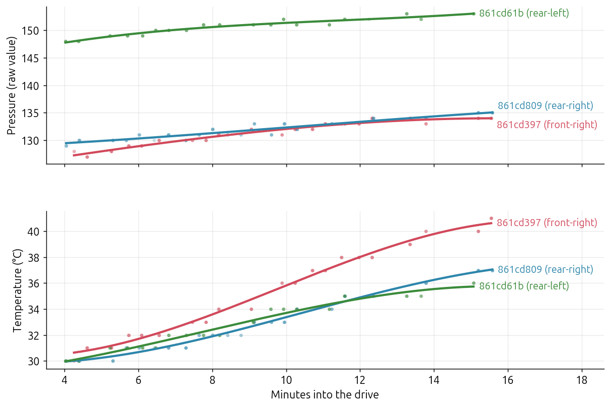 My three sensors on a drive, labelled with the positions. Top: time vs pressure, where the rear-left has higher pressure than the others. Bottom: time vs temperature in °C, where the front tyre warms up much faster than the two rear ones
A few days later I went to the workshop to get the new sensor fitted, and I sat with the staff there while they debugged the issue using an on-board diagnostics (OBD) tool. This is a tool that plugs into the car’s OBD port and reads data from the car’s computers over its internal network, the CAN bus. The OBD tool showed the ID registered for each wheel, and all three matched what I had worked out. It also gave me the ID of the new sensor, 9187740a, which I have been tracking ever since. The label on the broken front-left sensor showed that it had been 861cd414, which is why I never saw it in my logs.
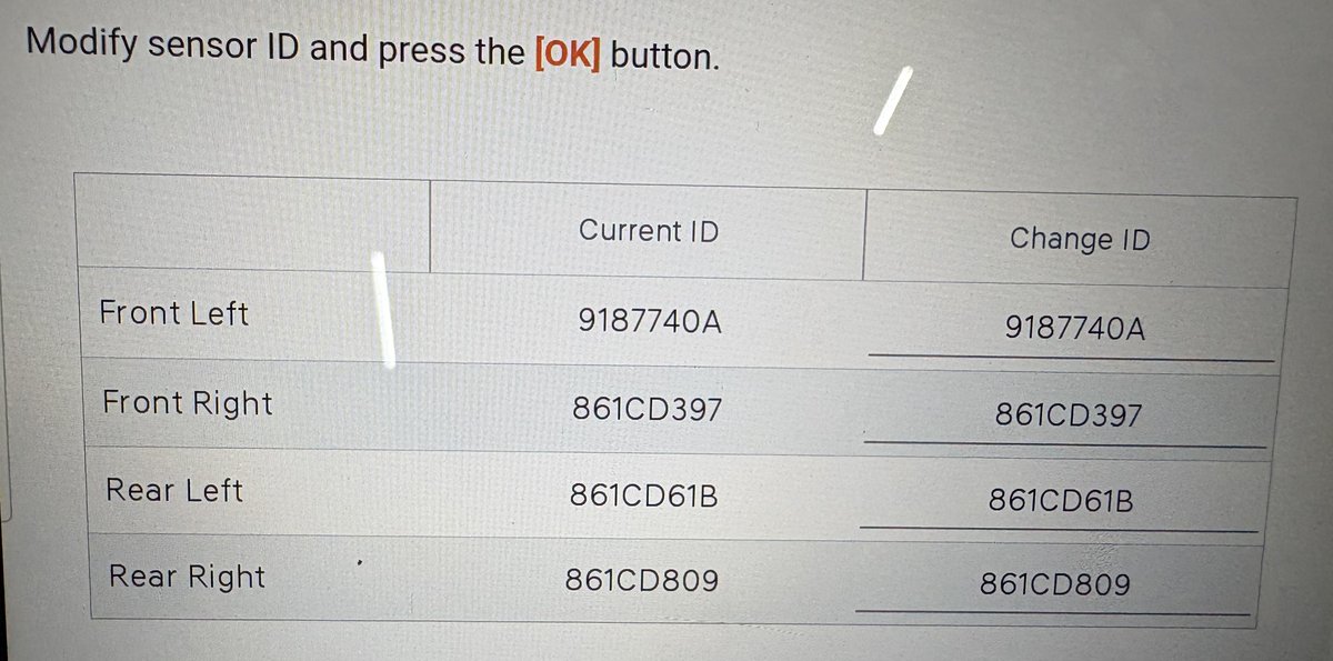 The workshop’s OBD tool showing the sensor ID registered for each wheel
| Wheel | Sensor ID | How I worked it out |
|---|---|---|
| Rear-left | 861cd61b | Highest pressure, matching the tyre gauge |
| Front-right | 861cd397 | Heated up the most on the drive |
| Rear-right | 861cd809 | Warmed up like a rear tyre |
| Front-left | 9187740a | New sensor, read from the OBD tool |
Getting the bits out
Now comes the part where we decode what is inside the packet. Before doing anything, I first needed to know how my sensors send their bits. As we saw in Part 4, there are two common ways these kinds of sensors do it: ASK, where the signal switches on and off, and FSK, where it hops between two frequencies. To start with, we can use rtl_433 itself. It comes with an analyzer, which can be turned on with the -A flag and looks at a recording and guesses the modulation. The community made this tool specifically as a debugging aid for starting out on new sensors. Here recording.cu8 is an IQ recording of my car’s sensors. As you can see in the output below, for my car it saw the whole 9.4 ms packet (shown as the pulse width) as one single long pulse.
1
2
3
4
5
6
7
$ rtl_433 -A recording.cu8
Analyzing pulses...
Total count:    1,  width: 9.39 ms   (9389 S)
Pulse width distribution:
 [ 0] count:    1,  width: 9389 us [9389;9389]   (9389 S)
...
Guessing modulation: Single pulse detected. Probably Frequency Shift Keying or just noise...
That makes sense, because in FSK the signal strength stays the same and only the frequency changes, so there are no on and off pulses to see. A spectrogram shows the same thing. To see one for our IQ file, we can use the I/Q Spectrogram & Pulsedata web tool on triq.org, made by the same rtl_433 developers. You just drop the recording onto the page. As you can see below, each packet switches between two frequencies about 80 kHz apart, just like the Toyota packet in Part 4. And the FCC test report for my sensor, which we looked at in Part 2, lists the modulation as FSK, which confirms our theory.
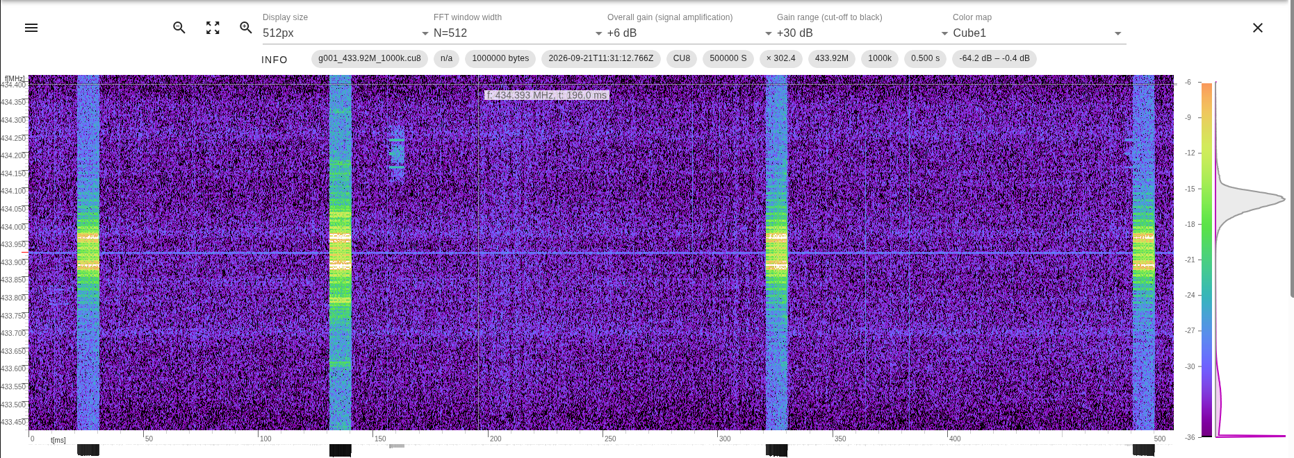 A burst of four packets from my front-left tyre in triq.org’s spectrogram tool. Each packet hops between two frequencies
Zooming in on the first packet as far as the tool allows, the two frequencies are easy to see, about 433.88 and 433.96 MHz, with faint vertical stripes where the signal keeps jumping from one to the other.
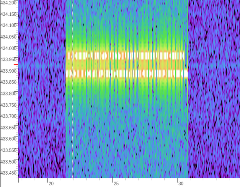 The first packet, zoomed in as far as the triq.org tool goes (time in ms)
Next I needed something that could turn that FSK signal into bits. rtl_433 has hundreds of decoders, and each one is written for a specific sensor. For cases like this, where a decoder is missing, rtl_433 also has a flex decoder. It is a general-purpose decoder you describe on the command line instead of writing in C, where you tell it the modulation, how long each symbol lasts and how a packet ends, and it slices the signal into raw bits without knowing what any of them mean. This is exactly the approach the rtl_433 guide to analyzing unknown devices recommends, and the full syntax is in the flex decoder docs.
The one thing I still needed was the symbol length, how long each symbol lasts. I didn’t measure it at first, I just guessed. Many FSK tyre sensors in the rtl_433 repository, including the Abarth and Ford decoders that had been decoding packets from my car, use 52 µs, so I tried that as a first experiment and ran rtl_433 on one of my recordings:
1
rtl_433 -R 0 -X 'n=my_car,m=FSK_PCM,s=52,l=52,r=150' -r recording.cu8
Here is what each part of the command does:
| Option | What it does |
|---|---|
-R 0 | Turns off every built-in decoder |
-X '...' | Adds a flex decoder, described by the options below |
n=my_car | Just a name, printed next to anything it finds |
m=FSK_PCM | The signal is FSK, with every symbol the same length |
s=52 | Each symbol lasts 52 µs |
l=52 | Same as s, since every symbol has the same length |
r=150 | Ends a packet after 150 µs of silence |
-r ... | Reads the IQ recording instead of listening live |
The guess worked, and out came four rows, one for each copy of the packet the sensor sends in a burst:
1
2
3
4
{178}55555556956956a5a65a966a5aa65556666956a59aa50
{178}55555556956956a5a65a966a5aa65656666956a5a5a50
{178}55555556956956a5a65a966a5aa65956666956a5a6a50
{178}55555556956956a5a65a966a5aa65a56666956a5a9a50
We will see in the next post why the sensor sends four packets in a single burst.
These are still Manchester encoded bits, not data. The bunch of 5s at the start is 0101 0101 ... in binary, the preamble the receiver uses to synchronize itself to the transmitter, and it ends with a 6, which is 0110 in binary, that breaks the pattern and marks where the data begins. The 144 bits after that are the actual packet, still Manchester encoded, so every pair of bits is one real bit, 10 for a 1 and 01 for a 0. We looked at how Manchester encoding works in Part 4. You can also see the tradeoff of Manchester encoding here. Each bit needs two symbols, so the packet is twice as long as the data inside it. If you want to know more about how the preamble and Manchester encoding keep the receiver in sync, I have listed some good tutorials under further reading at the end of this post.
Older versions of the flex decoder stop at raw bits. Newer ones, from version 25.12, can undo Manchester too, which we will use in the next post, but doing it by hand first shows what is going on. And the good part is that you don’t need to write any code for this. BitBench, a browser tool from the rtl_433 developers, takes rows like these and decodes them for you, and their guide to analyzing unknown devices recommends putting your codes into it. You just copy and paste the four rows into the tool.
Here are the settings I used on that page:
- Input: the four
{178}...rows from rtl_433, pasted as they are. The{178}tells BitBench each row is 178 bits long. - Coding: Manchester (G.E. Thomas), which turns every pair of bits into one.
- Show: Hex, so the result is easy to compare with the bytes below.
- Format string:
16x ID:32h 8h 8h 8h 8h CHECKSUM:8h, which skips the 16 bits that come from the preamble, prints the 4-byte ID in one piece and then the remaining bytes one by one.
Everything else was left at its default value.
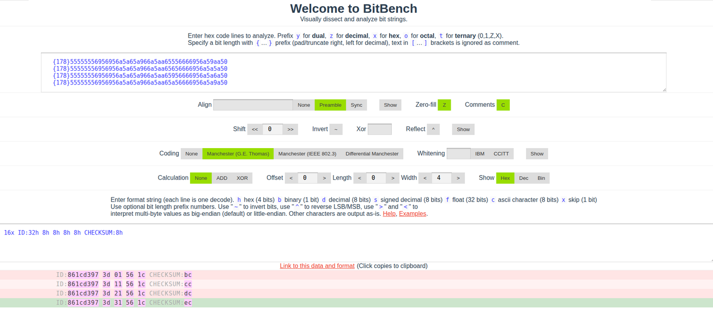 My four rows decoded in BitBench with Manchester (G.E. Thomas), with the ID right at the front of each one
But should 10 be a 1 or a 0? As we saw in Part 4, there is no single rule, and different systems do it differently. BitBench has both options, Manchester (G.E. Thomas), where 10 is a 1, and Manchester (IEEE 802.3), where 01 is a 1, so I didn’t have to guess. I tried both and only G.E. Thomas gave an ID I had already found in my logs. rtl_433’s own Manchester decoder, which I used later, follows IEEE 802.3, and with it my sensor’s ID comes out as 79e32c68 instead of 861cd397. Decoded with the right option, the 144 bits become 72 bits, or 9 bytes:
1
2
3
4
86 1c d3 97 3d 01 56 1c bc
86 1c d3 97 3d 11 56 1c cc
86 1c d3 97 3d 21 56 1c dc
86 1c d3 97 3d 31 56 1c ec
The first four bytes are the sensor’s ID, 861cd397, the front-right tyre. Out of the remaining five bytes, only the sixth and the last one change between the four copies. The last one is the subject of the next section, and the rest I will come back to in the next post.
Cracking the checksum
The last byte of every packet is a checksum, a small number calculated from the other bytes so the receiver can tell if anything got corrupted on the way. There is a nice video on checksums under further reading if you want to learn more. The four copies above gave away how it works. Between copies, the sixth byte goes up by 0x10 (01, 11, 21, 31) and the last byte goes up by exactly the same amount (bc, cc, dc, ec). That is what you would expect if the last byte is simply the sum of all the others.
And it is. Add up the first eight bytes and keep only the lowest byte of the result:
1
86 + 1c + d3 + 97 + 3d + 01 + 56 + 1c = 2bc  ->  bc
which is exactly the last byte. This held for every single packet from all my sensors.
Further reading
If you want to dig deeper into some of the ideas in this post, these are the tutorials I found most helpful:
- Clock synchronization and Manchester coding, a video by Ben Eater on how Manchester encoding keeps the receiver’s clock in sync with the transmitter
- Synchronization, a chapter of the free online book PySDR on how a receiver uses the preamble to find a packet and sync to it
- Checksums and Hamming distance, a video by Ben Eater on how checksums catch corrupted data
Coming up
So I could now find my car’s packets, get the bits out of them and check that they were not corrupted. What the remaining bytes actually mean is the next step.
Coming up in this series:
- Turning the bytes into pressure and temperature (Part 6) with the help of a digital tyre pressure gauge, and the one byte I couldn’t explain
- The different modes of a sensor, and what happens when I let the air out of my tyre
- Contributing my decoder to rtl_433
- Building a surveillance lab in my glovebox to collect data on every drive
- Why the sensor measures temperature
- Doing all kinds of data analysis on the data collected, with a lot more interesting plots like the one of my tyres warming up in this post
Stay tuned.